DRAGON PRODUCTS COMPANY'S CEMENT KILN DUST
Source: Dragon Products Company letter to MDEP Commissioner 3/12/98
INTRODUCTION
The purpose of this document is to summarize available material on a by-product generated by Dragon Products Company from the cement manufacturing process. This material known as cement kiln dust (CKD) or Dragon's trade name of K-Lime is a valuable by-product that has numerous outlets for beneficial reuse. The discussion that follows presents an overview of how the material is generated, the physical and chemical properties, current management practices and potential avenues for beneficial reuse.
SITE SETTING AND OPERATIONAL HISTORY
The Dragon Products Company's (Dragon) cement manufacturing facility is located off Route 1 in Thomaston, Maine, approximately two miles south of the town of Rockland. The Dragon Products facility has the distinction of being New England's only cement manufacturing facility. Nearest comparable (though significantly larger) facilities are located in New York's Hudson Valley and in the Canadian Province of Quebec. The Thomaston facility employs over 100 people and produces approximately 500,000 tons of cement per year.
The cement manufacturing facility at Thomaston has been operated by several owners since 1927. In 1988, Dragon was purchased by a consortium of Spanish companies. These companies have provided access to more advanced European processes and technologies that have improved the overall efficiency of the plant with regard to fuel usage and reintroduction of by-products. Many of these changes and improvements have occurred in the past five years.
Briefly, the cement-making process begins with the raw feedstock of calcium carbonate bearing rock and other products including silica dioxide (sand) and iron ore. The rock is quarried, crushed, and mixed with water to form a slurry. The slurry enters the sloping cement kiln where it is transformed through super heating. The cement kiln operates at temperatures exceeding 2500 degrees Fahrenheit. The heating process drives off the water and carbon-dioxide and crystallizes the input materials into an interim product known as clinker. Granular material that is not incorporated in the clinker may be entrained in hot high velocity gases that move contrary to the slope of the kiln. These particles constitute cement kiln dust. A schematic diagram of the cement making process is included as Figure 1.
CEMENT KILN DUST - WHAT IS IT?
Cement Kiln Dust (CKD) is a gray fine-grained mixture of partially calcined and unreacted raw feedstock. Although referred to as "dust", grain-size analyses of the material indicate that the a portion of the material includes a coarse to fine sand-sized particle fraction.
Average chemical composition of CKD avaiIable in the Iiterature describes a typical CKD as composed of constituents of the raw feed stock including calcium carbonate, silica dioxide, metallic oxides, calcium oxides, alkali chlorides and sulfates.
Samples of the material have been submitted for laboratory analysis. These samples were analyzed for total metals and dioxin/furans and are summarized below.

Notes: TCLP metals data were also acquired for samples CS-1 through CS-8. With the exception of CS-1 TCLP metals were below detection limits for the targeted compounds. Analysis of CS-1 revealed chromium concentrations of 0.1 mg/L.
CKD MANAGEMENT
Several important management changes have occurred over the operating history of the plant with regard to the handling, disposal and reuse of the cement kiln dust. Prior to 1970, the material was released directly to the environment and was dispersed to the local area by wind. In the early 1970s, dust collection systems were brought on line. Material is collected in a cyclone with finer particles collected in a filter array known as the baghouse. The accumulated material is mixed with water, placed in a truck and deposited in the area of a former schist quarry. A water content of approximately 10% allows for the management of the material with minimal fugitive dust emissions. 1997 ushered in significant infrastructure modification to the plant which has greatly facilitated dust ----------------------------------
page 3
collection and reuse. In April 1997, Dragon implemented modifications to the cement kiln to allow direct and self-contained reintroduction of baghouse dust back into the kiln as raw feedstock. The kiln dust scoops and attendant conveyors are enclosed and vented through fabric filter (baghouse) dust collectors. The dust scoops came on-line in May, 1997. As demonstrated by the following table, the dust scoops have significantly increased the amount of material re-introduced in the process with the associated reduction of material removed from the process stream.
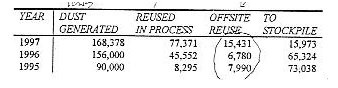
NOTES
Dust generated reflects potential tonnage if removed from system.
Final stockpile numbers reflect net material (material removed is deducted from total).
Off site Reuse may include "old" and "new" dust
1996 and 1995 numbers are pproximated from available data.
The 1997 data reflect the dramatic decrease in dust generated from approximately 8 months of operation with the newly installed dust scoops. We are optimistic that this improvement will increase in 1998
CKD PILE DSCRIPTION
In the Fall of 1997, aerial photos were flown for the CKD pile. These photos were completed by Aerial Survey and Photo, Inc. of Norridgewock, Maine and a copy of the photo is included as Figure 2. Dragon commissioned these photos to calculate stockpile volumes as part of a program to plan for reuse and to facilitate or identify other outlets of the material. A topographic plan of the pile and volume calculations were also completed by Aerial Survey and Photo, Inc. The plan map is included as Figure 3. The survey estimate for October 1997, was that the pile contained 958,771 cubic yards of material. This volume was calculated using the 60 foot elevation contour. By estimating the density of the material as 65 pounds per cubic foot, this equates to 841,322 tons of material. Both the photos and the map show an excavation in the southeastern corner of the pile. This excavation is the area where material is used for reincorporation in the process, or sold for agricultural or other beneficial reuse.
LEACHATE COLLECTION
Leachate from the CKD collects in a former quarry (Quarry 4). In 1997, Dragon, in cooperation with the DEP Water Bureau modified our wastewater collection and process water usage system. The revision of the wastewater treatment system involves the
-------------------------------------------------------- . . .
incorporation into the manufacturing process of the following waste streams: septic wastewater; leachate from the cement kiln dust; and leachate from the clinker pile. (1)
Historically, septic wastewater had been collected in a series of tanks, piped to a benned lagoon, disinfected by chlorination, and discharged into Quarry 5. Quarry 5 also collects leachate from both the CKD pile and the clinker pile as well surface/storm water flow (by far the largest volumetric input into Q5). The water from Q5 was pH adjusted with sulfuric acid, pumped to a constructed settling pond for final passive treatment and aeration before final discharge by gravity flow to an unnamed tributary of the St. George River.
The clinker leachate was formerly conveyed via an open ditch to Quarry 5 for treatment. With the recent modifications, the clinker leachate is now pumped via newly installed buried pipe to a wet well at quarry 5 where the alkaline water is used to disinfect the septic wastewater stream. The water is then pumped to Quarry 4 and eventually to the cement plant for use as process water. Approximately 80 gpm, of water from Quarry 4 is (2) being pumped into the raw mill, the rotary drum-like device in which water is added to pulverized stone, iron ore, and sand to make the slurry which is ultimately pumped into the cement kiln as process material input.
This system is currently under review and modifications are planned for Spring 1998. We are currently evaluating the feasibility of increasing the pumping inputs to the raw mill from Quarry 4, the optimal water levels through out the system and a contingency plan for high water events.
GROUND WATER MONITORING
Monitoring wells were installed around the CKD pile in December 1989. The drilling and monitoring well installation were completed by Northeast Diamond Drilling under oversight by Morrison Geotechnical Engineers. The exploration program is described in detail in a report prepared by MGE entitled A Report to Dragon Products Company on the Subsurface Conditions At the Two Solid Waste Facilities At the Cement Plant in Thomaston, Maine dated May, 1991. Briefly, three monitoring well clusters of three wells (3) each were installed around the CKD pile. The criteria for well installation were deep well installed in shallow bedrock, deep overburden well installed at the top of bedrock, shallow overburden well installed at the water table surface.
Subsequent to the installation of the wells, ground water samples were collected from the wells by MGE in July and November 1990 and in March 1991. The samples were analyzed for a comprehensive list of parameters based on the Solid Waste Regulations Chapter 401. Based on the results of these analyses, MGE proposed a recommended indicator parameter list. This effort was also described in the report referenced above. (4) d,d W e- 15 A summary of key parameters collected by Dragon since 1990 are included in Appendix A. In addition pH (5) is monitored at various points(6) around the leachate
Penciled-in notes:
(1) Not notified till late 1997
(2) unlined
(3) Check map for well locations
(4) Quarterly monitoring?
(5) Where are results. See appendix.
(6) see regs for sampling & analytical program.
--------------------------------------------------------------------------------
collection/wastewater closed loop. The next round of sampling and analysis is planned for April 1998.
REUSE OPTIONS
Through system upgrades and operational controls, Dragon has not only significantly reduced the volume of waste generated, but also has increased the amount of waste material reintroduced into the cement-making process for recycling. Dragon is also evaluating additional ways to increase the beneficial reuse of this material. (*)Planning is under way and will be outlined in supplemental information. Areas currently being pursued are agronomic reuse(2) and geotechnical avnlications.
Pencil notes:
(1) any applications submitted or approved by DEP?
(2) Sludge & resid.
---------------------------------------------------------------------
END